SEARCH WHAT YOU WANT

2026-04-21
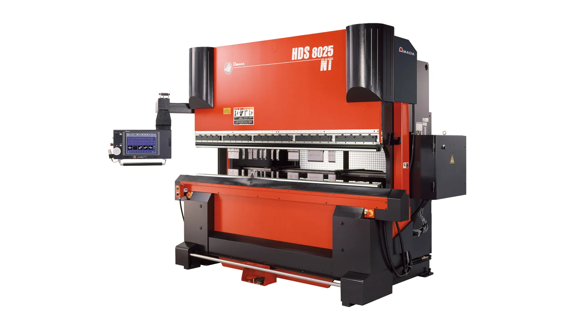
AMADA HDS 8025 NT Press Brake Operation Guide
1. Structure of the Laser-compatible Press Brake
1.1 Components
(1) Mechanical System
(2) Electrical System
(3) Hydraulic System
(4) NC Control System
1.2 Bending Method
Up-stroking: The lower die is fixed to the machine frame. Bending is performed by the upper die moving downward. The D-axis, L-axis, Y-axis, and Z-axis are all automatically controlled by the machine's CNC.
2. Operation Method
2.1 Power ON Sequence
(1) Main Power Switch of the Machine
(2) PLC Control Panel Switch (Wait for the panel to boot into the program before proceeding)
(3) Motor Switch
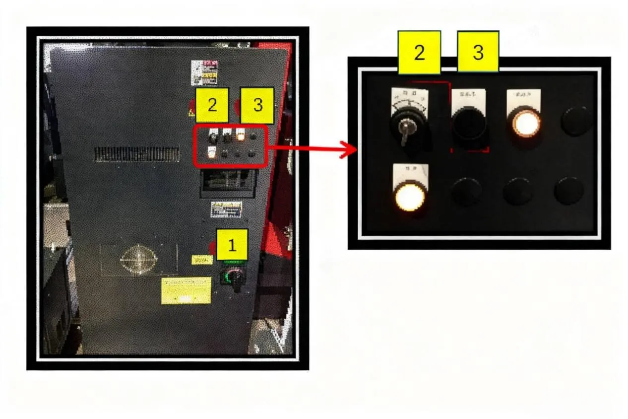
2.2 Power OFF Sequence
(1)Motor Switch
(2)PLC Control Panel Switch (Wait for the panel response before proceeding)
(3)Main Power Switch of the Machine
3.Manual Input & Program Input Procedure and Method
3.1 Preparation of Auxiliary Tools
(1)Vernier Caliper and Protractor: For inspecting if the product specifications meet drawing requirements.
(2)Red Wrench: Used for locking the lower die holder to the machine bed.
(3)Blue Wrench: Used for adjusting the slides/rails of the lower die holder.
(4)Yellow Hex Key: Used for adjusting the upper die clamping blocks on the machine, and for securing the lower die to the lower die holder.
(5)Green Hex Wrench: Used for securing fixtures for simple dies.
(6)Purple Hex Key: Used for locking the lower die to the lower die holder.
3.2 Process and Drawing Confirmation
(1)First, confirm whether pre-bending processes are completed, e.g., PEM nut insertion, tapping.
(2)Then, confirm the drawing matches the workpiece (sheet thickness, material), and check the workpiece for defects from previous processes. Reject NG workpieces and return them to the previous station.
(3)Next, check the work order for existing program records. If available, proceed directly to bending.
3.3 Tool and Die Selection, Die Changing
Place the engineering drawing on the machine. Use the purple hex key and red wrench to secure the dies onto the machine.
3.4 Setting the [Setup Screen]
3.4.1 Origin Return Procedure
(1) Access the [Setup] screen.
(2) Press the [Origin Return] key.
(3) Confirm the origin return screen is displayed.
(4) Press the [Start] key.
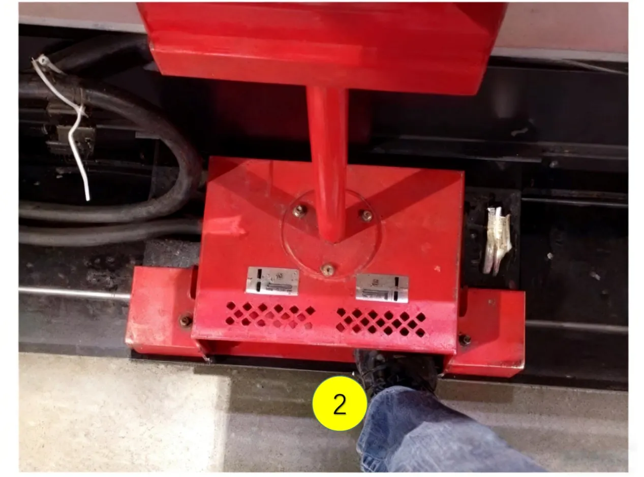
(5) Depress the die closing pedal.
(6) The back gauge will then perform the return-to-origin operation.
(7) A beep sound indicates the origin return is complete.
3.4.2 Tool Zero Point Setting
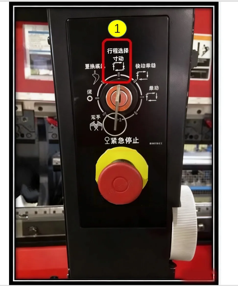
(1) Switch to [Jog Mode].
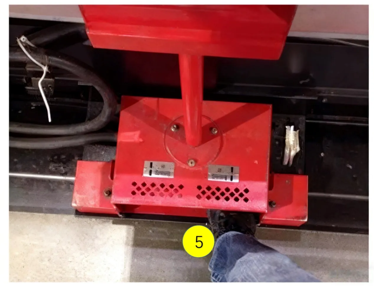
(2) Depress and hold the die closing pedal.
(3) Select the 5x speed rate (to increase the upper die descent speed).
(4) Turn the handwheel clockwise to gradually close the upper and lower dies.
(5) Stop turning the handwheel when the closing pressure (P) reaches 0.8~1.5.
(6) Press the [SET] key; only then release the die opening pedal. Open the dies to the maximum position.
(7) The "Tool Zero Point Setting Complete" screen will be displayed.
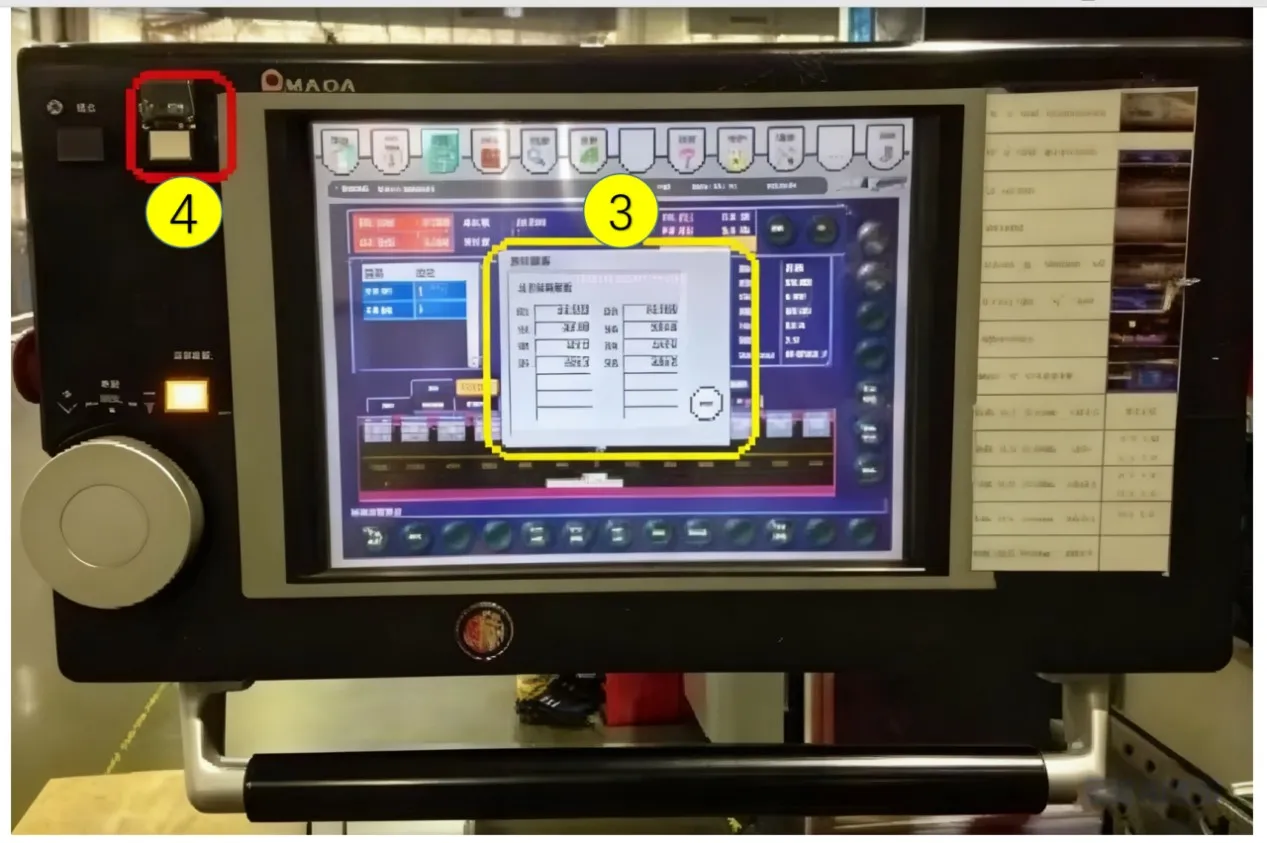
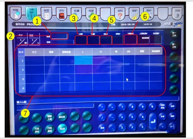
3.5 Setting the [Tool Program Screen]
3.5.1 Based on Bending Drawing Annotations
(1) Input Material Thickness
(2) Input Material Type
(3) Input Upper Die Specification
(4) Input Lower Die Specification
(5) Input Lower Die Holder Specification
(6) Input Die Cushion Specification (if applicable)
(7) Input Bending Parameters
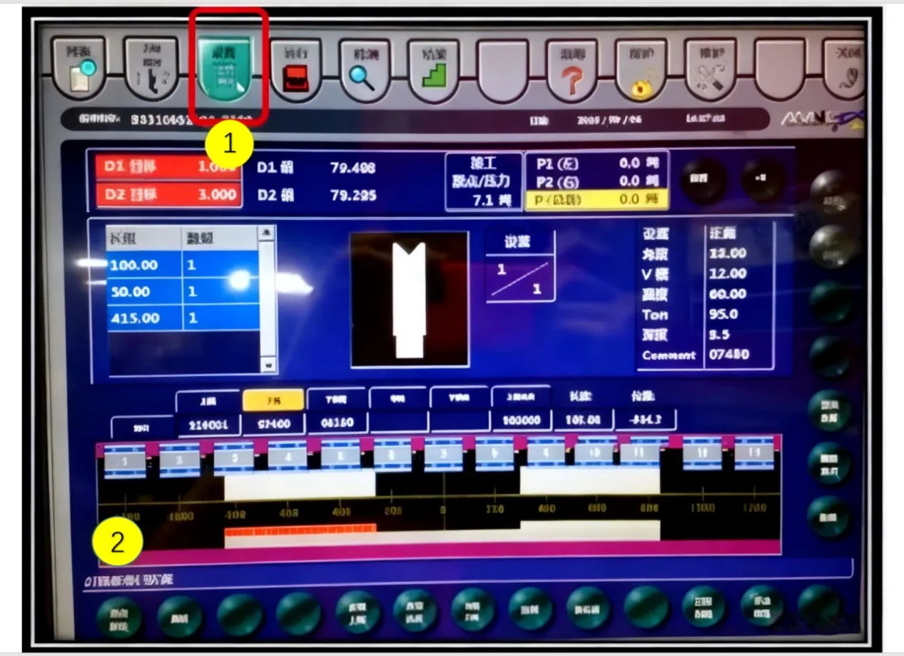
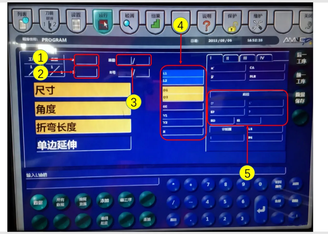
3.6 Setting the [Operation Screen]
(1) Overall Bending Dimension Compensation
(2) Overall Bending Angle Compensation
(3) Parts Counter Setting
(4) Back Gauge Fine Adjustment Setting
(5) Back Gauge Retraction Setting
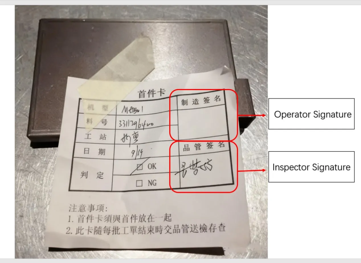
3.7 First-Article Inspection
(1) Operator verifies dimensions and angles.
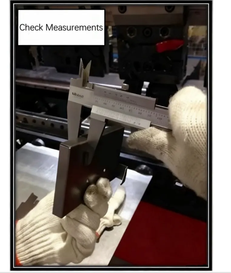
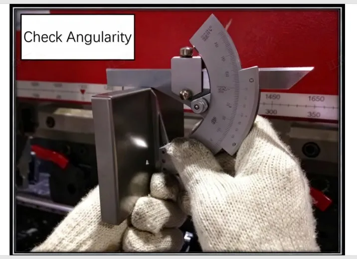
(2) After confirmation by the operator, send the first article to Quality Control (QC) for First Article Inspection (FAI).
(3) If deviations in dimensions/angles, or incorrect bend direction are found, make immediate corrections. Resubmit the corrected part to QC.
(4) After the first article is approved, place it to the right side of the machine for reference by patrol inspectors.
1. Structure of the Laser-compatible Press Brake
1.1 Components
(1) Mechanical System
(2) Electrical System
(3) Hydraulic System
(4) NC Control System
1.2 Bending Method
Up-stroking: The lower die is fixed to the machine frame. Bending is performed by the upper die moving downward. The D-axis, L-axis, Y-axis, and Z-axis are all automatically controlled by the machine's CNC.
2. Operation Method
2.1 Power ON Sequence
(1) Main Power Switch of the Machine
(2) PLC Control Panel Switch (Wait for the panel to boot into the program before proceeding)
(3) Motor Switch
2.2 Power OFF Sequence
(1)Motor Switch
(2)PLC Control Panel Switch (Wait for the panel response before proceeding)
(3)Main Power Switch of the Machine
3.Manual Input & Program Input Procedure and Method
3.1 Preparation of Auxiliary Tools
(1)Vernier Caliper and Protractor: For inspecting if the product specifications meet drawing requirements.
(2)Red Wrench: Used for locking the lower die holder to the machine bed.
(3)Blue Wrench: Used for adjusting the slides/rails of the lower die holder.
(4)Yellow Hex Key: Used for adjusting the upper die clamping blocks on the machine, and for securing the lower die to the lower die holder.
(5)Green Hex Wrench: Used for securing fixtures for simple dies.
(6)Purple Hex Key: Used for locking the lower die to the lower die holder.
3.2 Process and Drawing Confirmation
(1)First, confirm whether pre-bending processes are completed, e.g., PEM nut insertion, tapping.
(2)Then, confirm the drawing matches the workpiece (sheet thickness, material), and check the workpiece for defects from previous processes. Reject NG workpieces and return them to the previous station.
(3)Next, check the work order for existing program records. If available, proceed directly to bending.
3.3 Tool and Die Selection, Die Changing
Place the engineering drawing on the machine. Use the purple hex key and red wrench to secure the dies onto the machine.
3.4 Setting the [Setup Screen]
3.4.1 Origin Return Procedure
(1) Access the [Setup] screen.
(2) Press the [Origin Return] key.
(3) Confirm the origin return screen is displayed.
(4) Press the [Start] key.
(5) Depress the die closing pedal.
(6) The back gauge will then perform the return-to-origin operation.
(7) A beep sound indicates the origin return is complete.
3.4.2 Tool Zero Point Setting
(1) Switch to [Jog Mode].
(2) Depress and hold the die closing pedal.
(3) Select the 5x speed rate (to increase the upper die descent speed).
(4) Turn the handwheel clockwise to gradually close the upper and lower dies.
(5) Stop turning the handwheel when the closing pressure (P) reaches 0.8~1.5.
(6) Press the [SET] key; only then release the die opening pedal. Open the dies to the maximum position.
(7) The "Tool Zero Point Setting Complete" screen will be displayed.
3.5 Setting the [Tool Program Screen]
3.5.1 Based on Bending Drawing Annotations
(1) Input Material Thickness
(2) Input Material Type
(3) Input Upper Die Specification
(4) Input Lower Die Specification
(5) Input Lower Die Holder Specification
(6) Input Die Cushion Specification (if applicable)
(7) Input Bending Parameters
3.6 Setting the [Operation Screen]
(1) Overall Bending Dimension Compensation
(2) Overall Bending Angle Compensation
(3) Parts Counter Setting
(4) Back Gauge Fine Adjustment Setting
(5) Back Gauge Retraction Setting
3.7 First-Article Inspection
(1) Operator verifies dimensions and angles.
(2) After confirmation by the operator, send the first article to Quality Control (QC) for First Article Inspection (FAI).
(3) If deviations in dimensions/angles, or incorrect bend direction are found, make immediate corrections. Resubmit the corrected part to QC.
(4) After the first article is approved, place it to the right side of the machine for reference by patrol inspectors.
Next: Bending Auxiliary Tools
Recent Posts
Stay tuned for more updates

Need to reach us?
Leaders in industrial manufacturing & technology since 1992.