SEARCH WHAT YOU WANT

2026-04-21
Why I Believe in Custom Press Brake Tooling—Special Tools
Let me tell you the truth. I considered tooling to be a commodity at the beginning of my career. I made do with what was in the rack, used standard dies, and spent half of my shift adjusting the machine to make up for a bad fit.
Custom press brake tooling is not merely a manufacturing option; it is a strategic shift toward product-centric engineering. By designing tooling specifically for your end product, you transform the manufacturing process from passive execution into active value creation.
1. Why Do You Need Customized Press Brake Tooling?
I’ve discovered over the years that having the proper tool in the ram is more important for success in sheet metal fabrication than simply having a large press brake. My entire strategy has changed from “making the part fit the tool” to “making the tool fit the product.”
Here’s why, in my opinion, the only wise option for serious fabricators on the shop floor is custom press brake tooling.
Efficiency and Cost Optimization: Custom dies reduce overall production costs by streamlining the process flow and frequently doing away with the need for secondary operations.
Ensuring Functionality & Aesthetics: They ensure that the finished product satisfies stringent functional and aesthetic standards, avoiding dimensional errors or surface scratches.
Material Protection: Different materials (e.g., stainless steel, aluminum, copper) react differently under pressure. Custom tooling is designed to handle specific material characteristics, minimizing damage like cracking or marring.
2. How to Design Custom Tooling Based on Product Characteristics
Designing tooling isn’t abstract for me; it’s a tactile process. Before I even open the CAD software, I hold the spec sheet (and often the actual material) in my hands.
Here is how I attack a new custom tool job:
Read the Material: Is it stainless? Springy aluminum? I need to know how it fights back. The thickness dictates my tonnage, but the grade dictates my radii and relief angles.
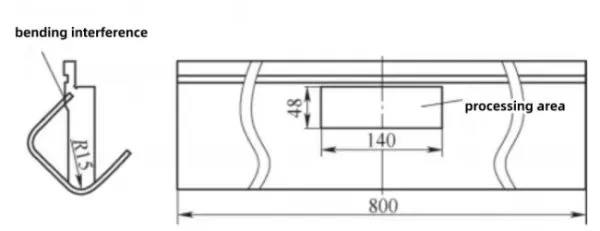
Anticipate the Collision: This is where most rookies fail. They design the bend, but they don’t design the escape. I constantly visualize the tool coming up. Will the next flange hit the die? I add strategic reliefs and cutouts not because the drawing tells me to, but because I know from experience.
In view of this interference phenomenon, the local machining method is used for the bending upper die. A notch of 140 mm × 48 mm is cut along the midline on the existing R15 mm straight knife upper die (L = 800 mm) (P1). The notch position is determined in combination with the simulated bending interference position without affecting its original function. After modifying the bending die, the bending interference problem was successfully solved.(video1)
video 1
CAD Modelling and Simulation:
Never go straight to the shop floor. Use software to simulate the bending process(video2):
- Verify the bending sequence.
- Predict springback.
- Check for collisions between the tooling, the workpiece, and the machine.
3. A Story from the Trenches: The Wave Part
Let me tell you about a job that proved the point. We had a decorative stainless steel part with a wave profile. Using standard tools, we were getting marks, the radii were wrong, and we were losing 20% of the parts to scrap.
Here is what I did differently:
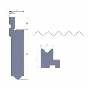
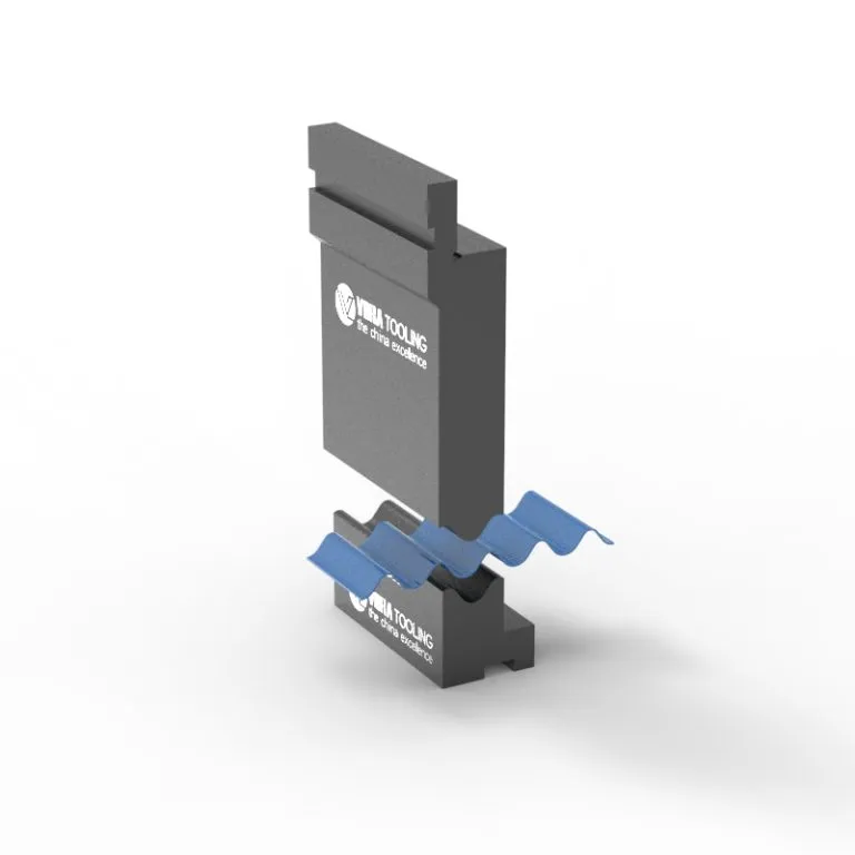
- The Match: I didn’t guess the radius. I designed the punch tip to match the trough of the wave perfectly. Physics doesn’t lie—if the tool doesn’t match, the part won’t either. (P2)
- The Protection: Stainless steel scratches easily. I treated the tool surface like it was a piece of jewelry, polishing it to prevent marring. (P3)
- The Clearance: This was the kicker. To get that wave shape, I had to cut reliefs into the sides of the tool. It looked strange on the drawing, but when we ran it, the part slid in and out perfectly. No binding. No bruising. (Video 3)
We went from 80% yield to 99.9% with that custom setup. That’s not luck; that’s engineering.
4. Conclusion: From Passive Execution to Strategic Advantage
I used to see myself as just a guy running a machine. Now, I see myself as a problem solver.
Using standard tooling keeps you in “mechanic mode”—reacting to issues, adjusting angles, and fighting springback. But designing and using custom tooling puts you in “craftsman mode.” You control the process.
The logic is simple: traditional “universal tooling” forces you to compromise on design, speed, or quality. In contrast, product-centric tooling ensures that every radius, angle, and sequence directly responds to the product’s functional and aesthetic definition.
For the Global Buyer:
Investing in custom tooling means investing in:
- Shorter Time-to-Market: Fewer setups and adjustments.
- Higher Quality Consistency: Reduced rework and waste.
- Market Agility: The ability to bid on and produce complex, high-value parts that competitors cannot.
Let me tell you the truth. I considered tooling to be a commodity at the beginning of my career. I made do with what was in the rack, used standard dies, and spent half of my shift adjusting the machine to make up for a bad fit.
Custom press brake tooling is not merely a manufacturing option; it is a strategic shift toward product-centric engineering. By designing tooling specifically for your end product, you transform the manufacturing process from passive execution into active value creation.
1. Why Do You Need Customized Press Brake Tooling?
I’ve discovered over the years that having the proper tool in the ram is more important for success in sheet metal fabrication than simply having a large press brake. My entire strategy has changed from “making the part fit the tool” to “making the tool fit the product.”
Here’s why, in my opinion, the only wise option for serious fabricators on the shop floor is custom press brake tooling.
Efficiency and Cost Optimization: Custom dies reduce overall production costs by streamlining the process flow and frequently doing away with the need for secondary operations.
Ensuring Functionality & Aesthetics: They ensure that the finished product satisfies stringent functional and aesthetic standards, avoiding dimensional errors or surface scratches.
Material Protection: Different materials (e.g., stainless steel, aluminum, copper) react differently under pressure. Custom tooling is designed to handle specific material characteristics, minimizing damage like cracking or marring.
2. How to Design Custom Tooling Based on Product Characteristics
Designing tooling isn’t abstract for me; it’s a tactile process. Before I even open the CAD software, I hold the spec sheet (and often the actual material) in my hands.
Here is how I attack a new custom tool job:
Read the Material: Is it stainless? Springy aluminum? I need to know how it fights back. The thickness dictates my tonnage, but the grade dictates my radii and relief angles.
Anticipate the Collision: This is where most rookies fail. They design the bend, but they don’t design the escape. I constantly visualize the tool coming up. Will the next flange hit the die? I add strategic reliefs and cutouts not because the drawing tells me to, but because I know from experience.
In view of this interference phenomenon, the local machining method is used for the bending upper die. A notch of 140 mm × 48 mm is cut along the midline on the existing R15 mm straight knife upper die (L = 800 mm) (P1). The notch position is determined in combination with the simulated bending interference position without affecting its original function. After modifying the bending die, the bending interference problem was successfully solved.(video1)
video 1
CAD Modelling and Simulation:
Never go straight to the shop floor. Use software to simulate the bending process(video2):
- Verify the bending sequence.
- Predict springback.
- Check for collisions between the tooling, the workpiece, and the machine.
3. A Story from the Trenches: The Wave Part
Let me tell you about a job that proved the point. We had a decorative stainless steel part with a wave profile. Using standard tools, we were getting marks, the radii were wrong, and we were losing 20% of the parts to scrap.
Here is what I did differently:
- The Match: I didn’t guess the radius. I designed the punch tip to match the trough of the wave perfectly. Physics doesn’t lie—if the tool doesn’t match, the part won’t either. (P2)
- The Protection: Stainless steel scratches easily. I treated the tool surface like it was a piece of jewelry, polishing it to prevent marring. (P3)
- The Clearance: This was the kicker. To get that wave shape, I had to cut reliefs into the sides of the tool. It looked strange on the drawing, but when we ran it, the part slid in and out perfectly. No binding. No bruising. (Video 3)
We went from 80% yield to 99.9% with that custom setup. That’s not luck; that’s engineering.
4. Conclusion: From Passive Execution to Strategic Advantage
I used to see myself as just a guy running a machine. Now, I see myself as a problem solver.
Using standard tooling keeps you in “mechanic mode”—reacting to issues, adjusting angles, and fighting springback. But designing and using custom tooling puts you in “craftsman mode.” You control the process.
The logic is simple: traditional “universal tooling” forces you to compromise on design, speed, or quality. In contrast, product-centric tooling ensures that every radius, angle, and sequence directly responds to the product’s functional and aesthetic definition.
For the Global Buyer:
Investing in custom tooling means investing in:
- Shorter Time-to-Market: Fewer setups and adjustments.
- Higher Quality Consistency: Reduced rework and waste.
- Market Agility: The ability to bid on and produce complex, high-value parts that competitors cannot.
Recent Posts
Stay tuned for more updates

Need to reach us?
Leaders in industrial manufacturing & technology since 1992.